Calibration
Get started with multi-sensor calibration. Explore the video tutorial for a complete step-by-step guide using a 3-sensor front-facing configuration. We recommend starting with a 3-sensor front-facing configuration, as it is the simplest and quickest configuration to construct and calibrate.
In this page
Calibration Tutorial Video→\
Requirements →\
Getting a project ready for Calibration →\
Floor detection →\
Sensor alignment sampling →\
Speeding up the Calibration sample capture →\
Clearing a Calibration →\
Metrics and indicators →\
Refinement tools →\
Refining a Calibration →\
Validating a Calibration →\
Calibration Video Tutorial
Requirements
To follow along our step-by-step guide you will need:
- a PC matching these hardware specifications;
- Azure Kinects with USB & Power Cables;
- 3.5mm audio sync cables;
- Tripods, Stands, or other Grip Gear to hold the sensors;
- Aruco Calibration Chart with stand - see printing requirements.
Getting a project ready for Calibration
Depthkit uses a series of samples to calculate sensor alignment in two steps: sampling, and filtering. Sampling adds reference points for Depthkit to factor into the calibration, and filtering removes the low-quality samples based on certain conditions to get the calibration as precise as possible.
❗️ One Calibration per Project/Sensor Configuration
A Depthkit project contains one multi-sensor calibration per project. If you want to create a backup calibration or need to recalibrate because one or more of your sensors changes position, create a new Depthkit project and calibrate/capture in that new project.
Depthkit Studio + Cinema
We recommend starting with sensor-only Studio captures, but once you're comfortable with the workflow, you can experiment with Depthkit Studio + Cinema.
Start with a stable sensor configuration
A good calibration begins with a robust sensor configuration. In this example, we are using a 3-sensor front-facing configuration, as it is the simplest and quickest configuration to construct and calibrate.
Once you have calibrated for the first time with 3 sensors, add more devices based on your project needs.
- Secure the sensor support equipment into a stable position. Sensors which sag or move even the smallest amount will invalidate the calibration.
- Plug in all cables prior to starting the calibration. Even the movement of plugging in a cable can move a sensor enough to endanger the calibration.
Create your Project
- Launch Depthkit and ensure your license reads Depthkit Pilot. If your license was recently activated, you may need to click the refresh icon.\ Create a new project.

- The application will launch in the Pair Camera workspace. This context allows you to use the Depthkit Cinema workflow to pair a video camera to your depth sensor. For a complete guide on camera pairing, visit the Depthkit Cinema documentation.
Click the Studio Calibration & Recording tab to begin calibrating your sensors.

You can also navigate there by going to the View menu and selecting Studio Calibration & Recording.

-
Under Sensor Configurations, you will see all connected depth sensors. If you do not see all sensors, make sure all of your USB and power connections are secure, and click the refresh icon next to the number of sensors connected.
-
Here you can adjust the stream configuration, sensor video settings, and advanced settings. Set the following Stream Configuration for best results in your calibration. You can collapse the settings of each sensor to navigate easier.

- Set the Color Resolution to 720p for the best performance during calibration. This setting is for calibration only, and can be changed to a different resolution without needing to recalibrate once it's time to record.
- Select a Depth Mode of 1024x1024. This setting can also be changed without the need to recalibrate once it's time to record.\ Optionally click Apply Settings to All Sensors to copy the settings from one sensor to all connected sensors.
- You do not need to change the Sync Mode or Sync Delay. Once your synchronization cables are connected, the devices will be synchronized automatically during calibration. Do not touch these settings unless you run into synchronization issues.
Floor Detection
First we will establish the 3D origin and orientation of our scene. This is not mandatory, and doesn't affect sensor alignment, but it does ensure that the scene will be right-side-up and facing the proper direction when we later bring it into a 3D workspace.
🚧
As of Depthkit version 0.7.0, the bounding box used when processing Studio captures is aligned to the floor sample, so be sure that your calibration chart is flat against the floor when capturing the floor sample.
- Under Controls, click Start Calibrating.

- Place the chart flat on the floor in view of at least one sensor.
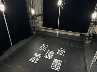
📘 Use multiple markers for more accurate floor samples.
If you have multiple calibration charts (each displaying unique markers so there are no redundancies), you can gather a more accurate floor sample by laying many charts on the floor, ensuring they are all oriented in the same direction (see the arrow at the top of our calibration chart PDF), and then capturing or replacing your floor sample. Depthkit will average the positions of all of the markers in the scene, and make that the origin of the asset. This will enable you to more easily remove the entire floor using the bounding box during editing.
📘 The floor sample can be determined by even just one camera perspective.
For the Floor Sample, you don't need the chart to be visible to all perspectives, which can be challenging in five or ten camera arrays. Choose a placement for the sample that is the actual floor and center point of your action, and as long as it's visible to some of the cameras your floor sample will be successful.

- Click Start Floor Detection. Wait five to ten seconds, and then click stop.
- Double-click to reset the view of the scene to the 'front' side of the origin point, and zoom out to see the whole volume.


- Depthkit will automatically select one of the sensors to reference the floor sample. You can override this by clicking any of the other sensors in the 'Floor Samples' panel to make that the anchor sensor. To revert back to the default sensor, click the 'Reset to default' button.
Replace Floor Sample
If you captured an erroneous floor sample, you can replace it by placing the chart in the correct position, then clicking the Replace Floor Sample button.
Sensor alignment sampling
When capturing alignment samples, focus on two neighboring sensors at a time. Be sure that the chosen sensors have overlapping fields of view. This is necessary because Depthkit calculates 'links' between pairs of sensors, and each link adds up to make a daisy-chain of these links.
The best calibrations include many samples from within the common volume of each pair of neighboring sensors.

Capturing samples
When sampling, make sure the chart is stationary. This includes letting the stand the chart is attached to come fully to rest after moving it.
- Choose a pair of sensors, and imagine a point directly between the two sensors and always face the chart directly towards that point. If the chart is pointed in any direction other than directly in between, the quality of the sample may suffer. Don't worry if other sensors outside of this pair can see the calibration chart. This will be filtered out by the calibration algorithm.

- Start with the chart as close to the sensors as possible while keeping the chart in view of both sensors. If the chart is in view of the sensors, you will see the corners of each marker highlighted with a circle.

- Click Start Sampling. Sample for 5 seconds, then click Stop Sampling.

- Once a sample is captured, clusters of dots, rings, and lines will appear. The dots and rings represent each sensor's view of a marker, and the lines represent which way each sensor perceives the chart to be facing.\ Capture samples at a couple of heights, adjusting the tilt of the chart so it faces the mid-point between the sensors during each sample.

- Next, move the chart back toward the center of the volume and capture samples at a few different heights.\ Throughout the sampling process, the goal is to capture samples at a few different heights, and also from sides of the frame, as well any other part of the volume where the performance will take place. Don't forget to move the calibration chart a bit beyond the center of the volume as well.\ Repeat this sequence for each pair of adjacent sensors. A 3-sensor configuration will only need enough samples for two links (\~40-50 samples total), but a 10-sensor configuration will need samples for nine links (\~175-200 samples total). There's no proper number of samples per link, but most successful calibration contain around 20-30 samples per link.
Speeding up the Calibration sample capture
A longer sampling duration generates a more accurate sample, however there are diminishing returns over more than a few seconds, so if calibrating a system needing many samples (e.g. one with 10 sensors), you can use shorter sampling durations like 2-3 seconds.
Different sensor configurations have different needs, but one way to speed up your calibration is to place more ArUco markers in the volume to calibrate more of it at once.

Keep in mind:
- All of the markers captured a given sample must be unique.
- Depthkit supports standard ArUco 4x4 markers up to ID #99. Using any other markers, including ArUco 4x4 markers with higher ID numbers, may invalidate your calibration. The complete set of supported markers can be downloaded here.
- All markers must still be printed and affixed in a way which keeps them visible to the IR camera in the depth sensor.
- The most accurate samples are those in which the marker directly faces toward the sensor. Markers captured at oblique/glancing angles may generate samples with higher errors, which may be filtered out with the Angle of Incidence slider, so be sure to still get plenty of samples from different positions and rotations, even if your calibration object has many markers.
- Putting your calibration object on wheels makes it much faster and easier to move around, but ensure that the markers remain stationary while the sample is taken.
In Depth Calibration Tutorial Video
📘 Older version used in tutorial
The Calibration interface has been updated since this tutorial was made. See above for update to date explanations of the tools.
Clearing a Calibration
The option to clear your Calibration is available in the Controls panel. If you want to delete your sensor Calibration and start again, click the trash can icon.
❗️ Clearing the calibration will delete all links and samples.
Calibrations should not be cleared if you have existing clips that will rely on this calibration, as this takes will no longer be aligned once the calibration is cleared. *Once a calibration is deleted, it cannot be recovered.
Metrics and indicators
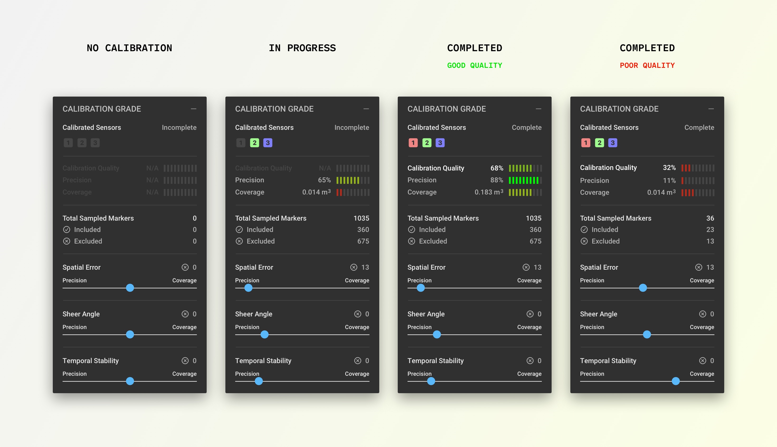
Calibration Complete/Incomplete indicates if all of the connected sensors have been linked together with the current calibration, or if any of the sensors are orphaned. Even when a calibration is marked 'Complete', the calibration may still need additional samples or adjustment to the filters to get the sensors to align well.
Calibration Quality is based on the mean squared error (MSE) divided by the sampled volume. This is to indicate the balance that must be stricken between a low MSE and a high sampled volume. Ideally this number is as close to 100% as possible. This is the main metric to look at to determine if your calibration is good or bad.
Precision is calculated based on the average of the distances (squared) between each respective sensor's view of a each sample.
Coverage displays the total volume sampled, which is calculated by adding up the number of unique sample positions captured during calibration. Filtering the samples closest to the sensors (often via lower Angle of Incidence) or farthest from the sensors (often via a lower Sample Deviation Threshold) will reduce the size of the volume. If this Sampled Volume is too small, the calibration will not align all areas of your capture volume well, so keep the Sampled Volume as high as possible.
Total Sampled Markers displays the total number of markers captured. This is often the number of samples captured multiplied by the number of markers on your chart.
Included displays how many markers have not been removed by the filtering tools.
Excluded displays how many markers have been removed by the filtering tools.
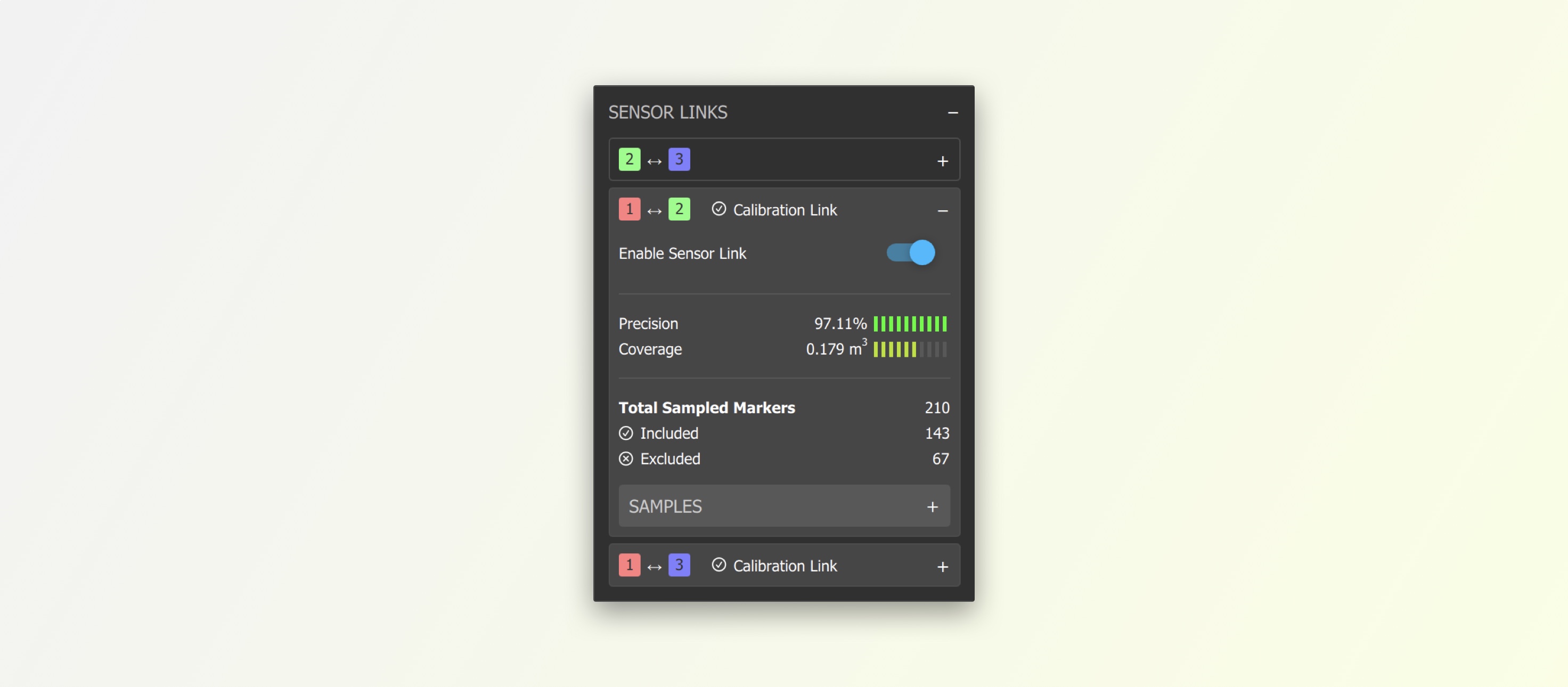
Per-Link Metrics provide this information for each link. If one particular link has a low sampled volume, you can capture more samples in view of those two specific sensors to fill out that link.
Refinement tools
Precision can increase calibration accuracy by filtering out select samples. Adjust this slider to reduce your Mean Square Error. Shift towards 'Precision' to filter out samples that have the longest lines between each dot in a cluster. Try to get this as close to the precision side as possible before the Precision metric begins to drop, or one of the sensors goes out of alignment.
Sheer Angle filters out samples where a sensor sees the chart at a sheer angle, which is less accurate than when the sensor sees the chart from straight on. Generally, lower is better, but it might need to be brought up to include some of the samples which are nearer to the sensors, or if sensors have a wide angle between them. By default this slider is set to filter out samples with an incident angle greater than 50°.
Temporal Stability filters out samples where the marker detection was inconsistent over the duration of the sample capture - for example, if the chart was bumped during capture, or was captured too far away from the sensor, resulting in additional depth noise. Lower is better here as well, but pushing it too low will unlink some of the sensors.
Sensor Links > Sensor Link Enable/Disable ☑️ If one sensor is particularly out of alignment, you toggle specific sensor links to see if rebuilding the link tree brings the sensor into better alignment.
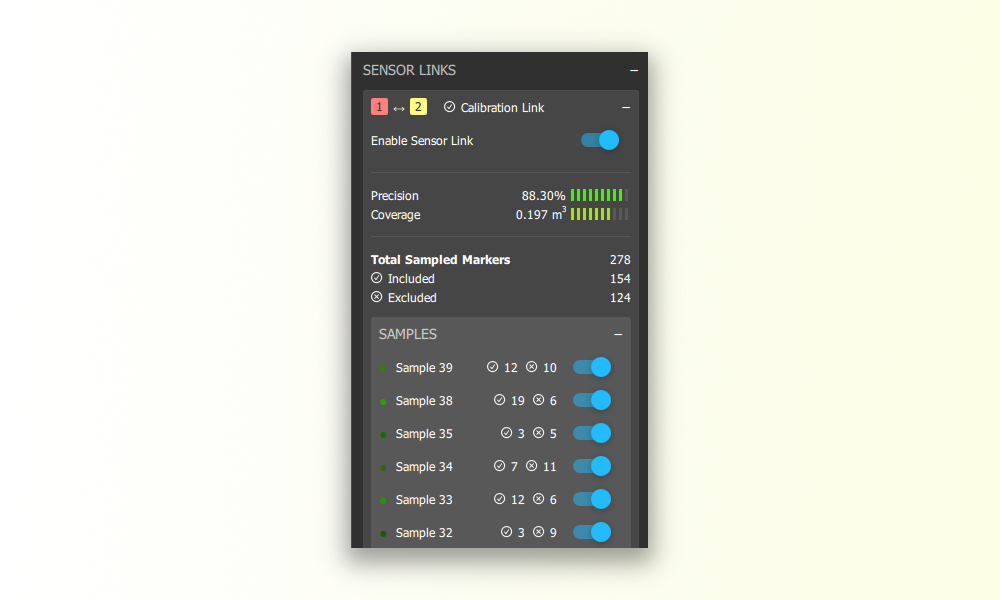
Sensor Links > Samples > Sample Enable/Disable ☑️ If one of your samples is causing issues (e.g. There was more than one chart in view of the sensors when the sample was captured), you can manually exclude that sample by expanding the link(s) that contains it, and disabling it.
Refining a Calibration
Refining often takes multiple passes of adjusting each filter and finding a combination of slider positions that results in the best metrics, as well as good visual alignment in the 3D viewport.
- If you have a Low Error and a Small Volume you should relax the Angle of Incidence and Sample Deviation filters to include more samples. Capture more samples to fill out the coverage and increase the sampled volume.
- If you have a Large Volume and a High Error note that this could be due to a number of factors, such as a calibration chart that is small, or poorly detected by the sensors, or unstable/oblique when captured.
To analyze your samples, zoom into the 3D viewport. It may be helpful to rotate the viewport so you are viewing samples from above to better understand the alignment.

Each set of samples is color coded based on the sensor perspective. In this tutorial, you can see red, green, and blue used for the sensor color coding.\ Aligned samples are represented by solid overlapping circles.

The hollow circles are outliers in your sample set. These are samples that have been filtered out.

Validating a Calibration
Evaluate in Depthkit Studio Calibration
There are many factors which dictate how precise the calibration needs to be. The calibration might perfectly align the sensors in one part of the volume, but not in another part, so be sure to check all areas of the volume that will be captured.
First ensure that your metrics are suitable. In general, a calibration with an overall quality of 80% or greater is good enough for most testing, and you only 100% quality when calibration quality is critical.
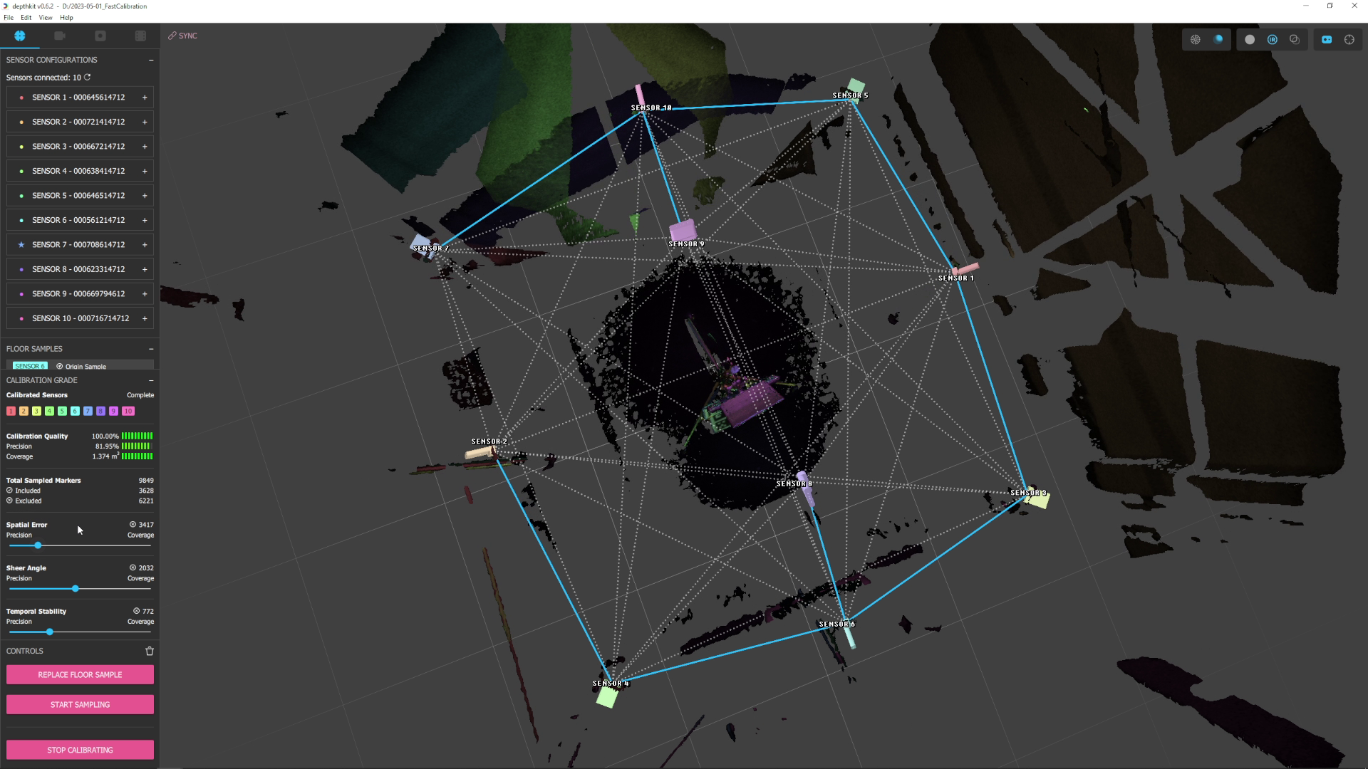
The active links in your calibration should join only the sensors nearest to each other, as in the blue links seen in this screenshot. Although the calibration process generates links for many combinations of sensors, the majority of these will be intentionally disabled (grayed and dashed). If the active links are not the ones joining the nearest
Have someone stand in, or place some stationary objects in the areas of the volume that will be captured, and begin streaming. Enable the Solid/Mesh rendering mode to see approximation of the sensor alignment. Have the subject hold out their hands with a single finger pointed up to see how well small details line up.
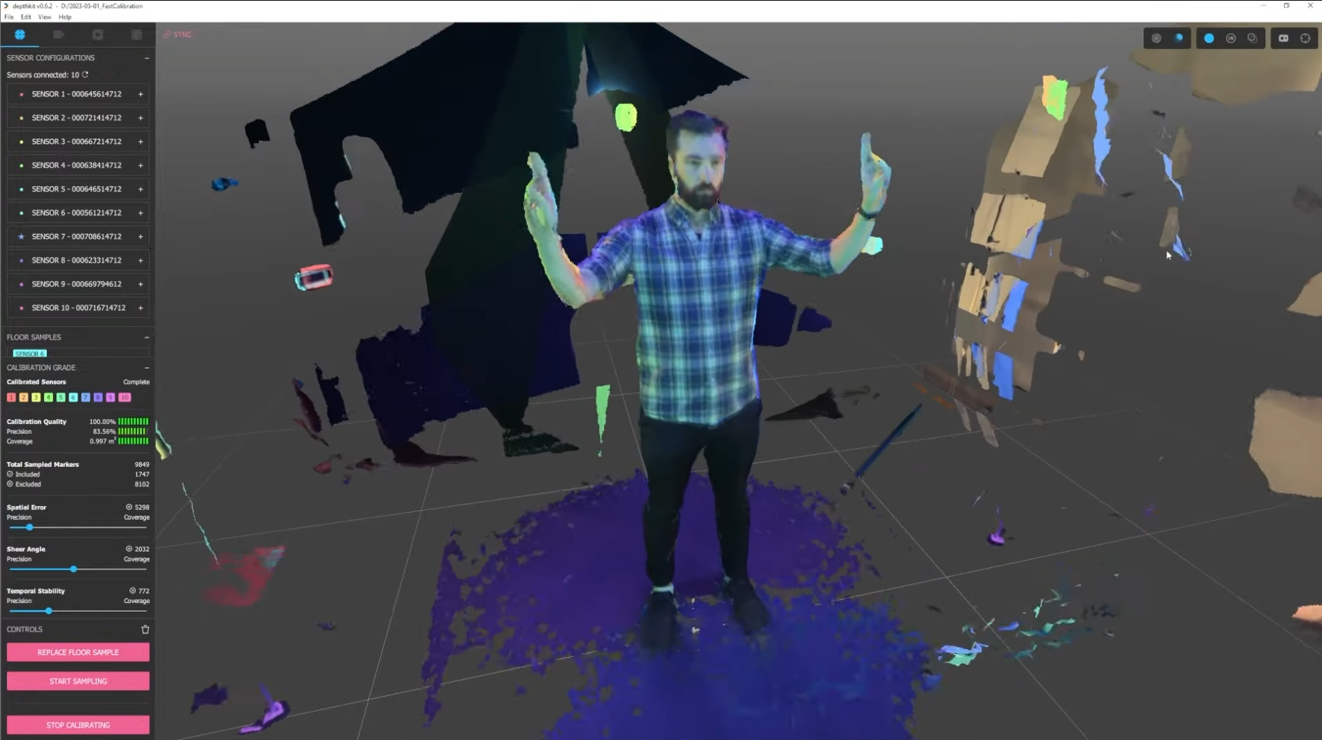
You can also enable the IR and Edge Detection texturing modes in the 3D viewport to see how well the sensors align with the current calibration.
Evaluate in Depthkit Studio Editor
Now that you have a completed calibration, you can record a test clip and quickly look at the fused capture right in the Depthkit editor. See the Processing Studio captures section for more information.
Preview live in Unity
Validating in a later stage of the pipeline like Unity is the best way to truly know that the calibration is up to the standards of the project. Click 'Stop Calibration', then 'Start Streaming' and recording or livestream a validation scene, then follow the Unity documentation and tutorials to setup the Depthkit Studio expansion package to visually assess alignment.