Depthkit Studio Expansion
The Depthkit Studio Expansion Package is designed for use with Depthkit Studio multi-sensor footage in Unity. It is also compatible with Depthkit Core and Depthkit Cinema clips.
🚧 Ensure Your Pipeline is Compatible
Before kicking off your production or committing to deliverables for your clients, we strongly recommend conducting an end to end test of your intended pipeline to ensure compatibility and performance for your deliverables.
See Depthkit Studio Platform Support for more details
In this page
Video tutorials →\
Package contents →\
Setting up a project →\
Creating a Depthkit Studio clip →\
Configuring a Depthkit clip →\
Video tutorials
(Expansion Package Phase 5 shown)
📘 Depthkit Studio Expansion Plug-in is supported with Unity 2020.3 LTS.
Users have had luck with other versions, but we cannot guarantee support on platforms other than 2020.3 LTS.
Package contents
This guide includes how to import and work with the Depthkit Studio Expansion package for Unity. It also includes how to create Depthkit clips in your scene.
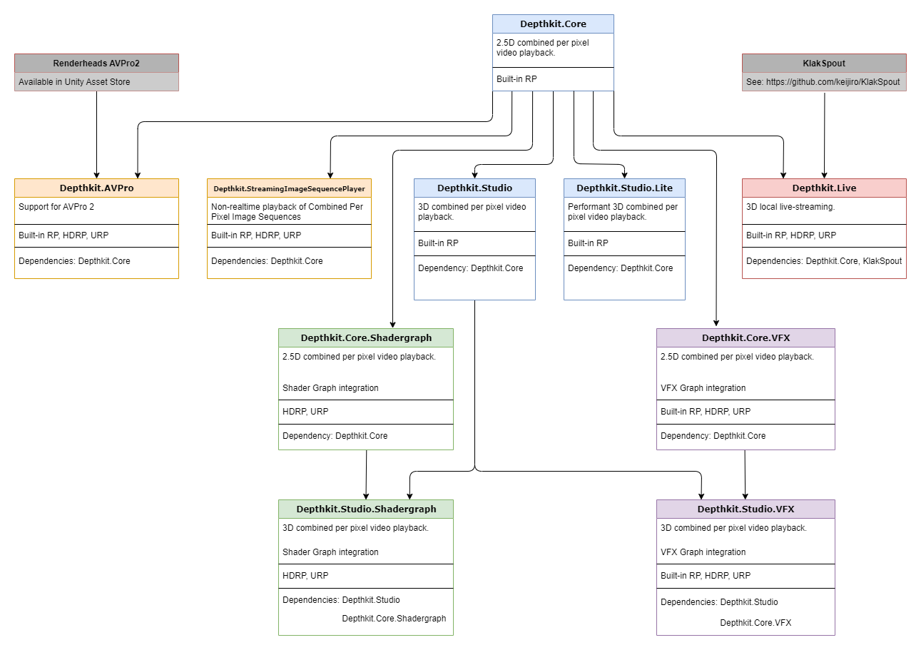
The Depthkit Studio Expansion Package (as of Phase 9) is made up of the following packages.
depthkit.core(0.13.2)depthkit.core.shadergraph(0.5.1)depthkit.core.vfx(0.5.2)depthkit.avpro(0.1.2)depthkit.studio(0.9.2)depthkit.studio.lite(0.1.0)depthkit.studio.shadergraph(0.4.2)depthkit.studio.vfx(0.4.2)depthkit.live(0.2.2)
The Depthkit Core package provides a direct integration with Unity and must be imported into your project prior to importing the Depthkit Studio packages.
The Depthkit AVPro package (introduced in Phase 6) adds support for Renderheads' AVPro 2 video player.
The Depthkit Studio is the primary package for optimized playback of 3D Depthkit Studio assets.
The Depthkit Studio Shader Graph package provides compatibility with Unity’s Scriptable Render Pipelines, including URP and HDRP. This package unlocks Depthkit’s support for the Shader Graph. Import this package via the Package Manager after importing the Depthkit Core and Depthkit Studio package.
The Depthkit Studio VFX package unlocks Depthkit’s support for the Visual Effect Graph. This package is compatible with Unity’s Scriptable Render Pipelines, including URP and HDRP. Import this package via the Package Manager after importing the Depthkit Core package and Depthkit Studio package.
The Depthkit Live package unlocks live-streaming with Depthkit Studio.
Package dependencies
Select packages act as dependencies when importing into your Unity project. See the dependency diagram below for import requirements.
Setting up a project
Import Packages via the Package Manager
- Go to the Package Manager and select In Project in the packages dropdown menu.
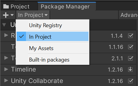
- Select the add icon and Add package from disk.

- Locate the
depthkit.corepackage folder. Within this folder, select thepackage.jsonfile and click Open.

- Repeat this step to import your desired Depthkit Studio packages.

- You will now see Depthkit Studio populated in your Package Manager. Select this item and expand Sample. Import the Depthkit Studio Built-in RP prefab.
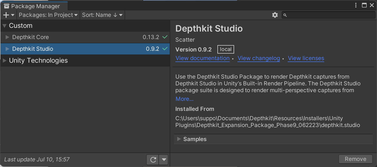
With the Depthkit Studio package, you can get started creating clips immediately in the Build in Render Pipeline.
If working in HDRP or URP, repeat this process for the Depthkit Shader Graph package(s) as found in the Shader Graph guide. If using the Visual Effect Graph, follow the steps in Visual Effect Graph.
Import Errors
If the Unity packages fail to load and you are seeing errors, see the Unity Packages fail to load section of our troubleshooting guide.
Creating a Depthkit Studio clip
You can create a Depthkit clip in two ways: by using the Depthkit Studio prefab provided in the package or by creating a clip via a game object.
Depthkit prefabs
Each Depthkit Studio package comes with a pre-configured Depthkit clip to get you up and running immediately. Prefabs can be imported via the Package Manager.
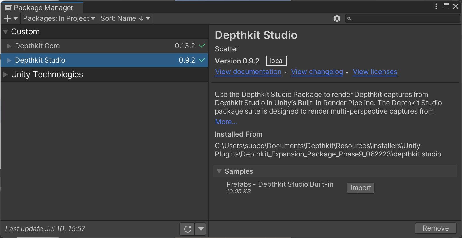
Once imported, the prefabs become available in your assets folder, in the Samples folder.

For each package, prefabs are available as a Depthkit Clip + Look or for the Look alone. To get started in your scene, simply drag Depthkit Clip + Studio Built-in RP Look (or other desired Look) into the Hierarchy.

📘 The Depthkit Core/Studio Built-in RP Look only works within the Built-in Render Pipeline.
To customize your Depthkit clip with the Shader Graph or when in HDRP/URP, begin with the provided Depthkit Clip + Core Shader Graph Look. When experimenting with the Visual Effect Graph, get started with the Depthkit Clip + Core VFX Look prefab.
Depthkit prefab compatibility
Depthkit prefabs are provided based on your project's render pipeline and rendering goals.
- The Depthkit Clip + Studio Built-in RP Look is compatible with the Built-in Render Pipeline. This prefab should not be used if working with a scriptable render pipeline.
- The Depthkit Clip + Studio Shader Graph Look is compatible with URP/HDRP and designed for Look development with the Shader Graph.
- The Depthkit Clip + Studio VFX Look is compatible with Built-in RP/URP/HDRP and designed for Look development with the Visual Effect Graph.
Creating a Depthkit clip from a Game Object
Alternatively to using a prefab, you can create a fresh Depthkit clip from scratch and assign your desired Look via the Component menu.
-
In the Hierarchy, right click and create an empty game object.
-
With the game object selected, go to the Component menu, select Depthkit → Depthkit Clip.

- With the game object still selected, head back to the Component menu and select Depthkit → Studio → and Built-in RP → Depthkit Studio Look Built-in RP or your desired Look.

Looks are provided for the Built-in Render Pipeline, the VFX Graph, and the Shader Graph. You can assign the Look that works for your creative needs in the Shader Graph and Visual Effect Graph guides.
Depthkit architecture: clips and Looks
Clips and Looks are separate entities. A clip houses a number of data sources that generate new data every time there is a new frame. Depthkit clips reference your Depthkit Combined Per Pixel video, metadata file, and optional poster image for each of your assets.
One or more Looks may use data generated by the clip data sources to draw it in different ways or in different places. The Look(s) can be placed on a different game object and reference any clip, as long as that clip is compatible with the look type.
Setting up your Depthkit clip
-
Create a Depthkit clip in the Hierarchy via a supplied prefab or via a new game object.
-
In the Project window, create a new folder under Assets. You can do this by right clicking in the Project window and selecting Create → Folder. I like to name this folder Clips. This will hold your Depthkit video files, metadata text files, and optional poster images. Drag your Depthkit assets into this folder in the Project window or copy and paste in the explorer window.
-
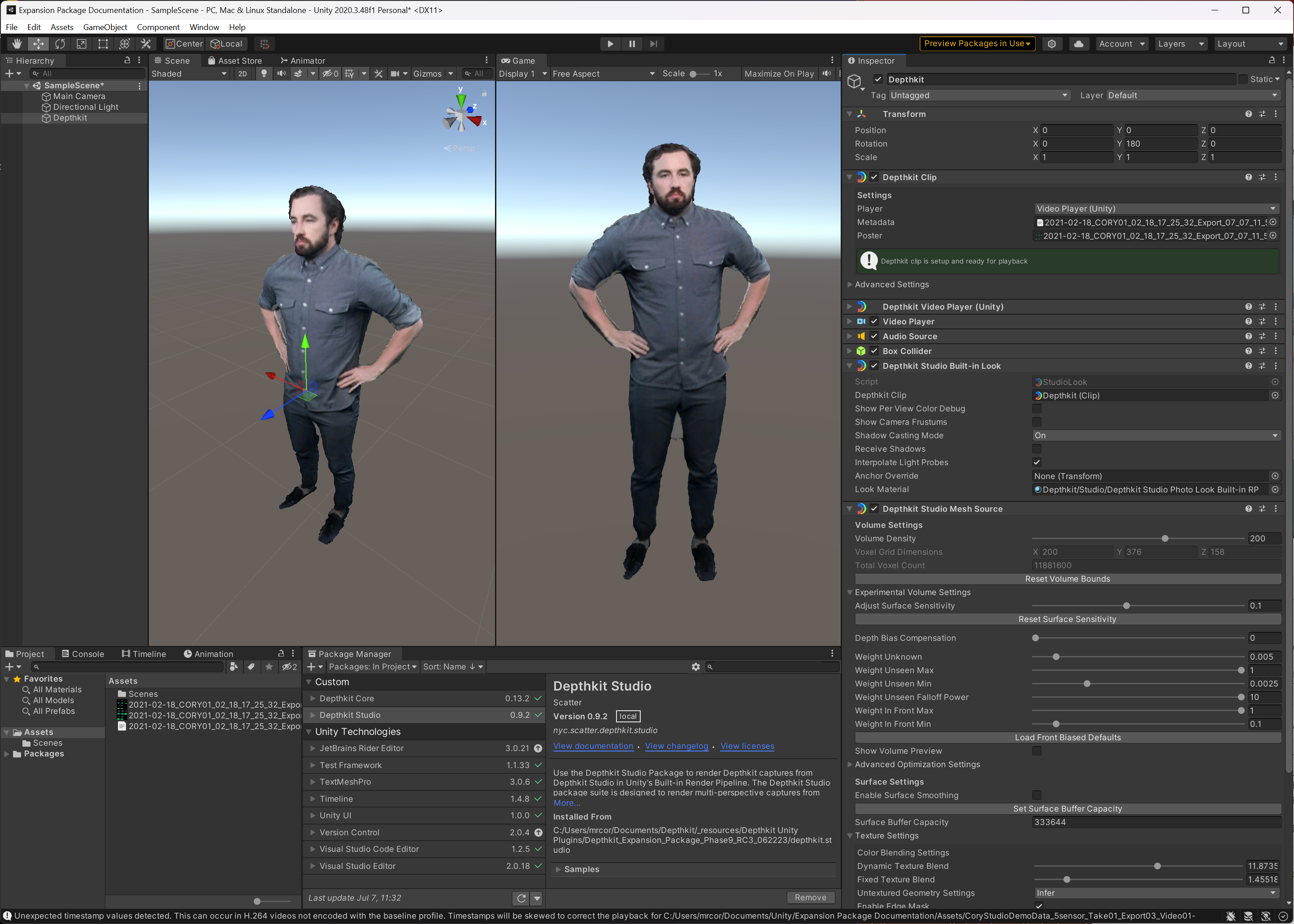
Back in the Hierarchy, select your recently created Depthkit Clip. See the Inspector. You will notice that the Depthkit Clip component is alerting you that your Depthkit Clip is not set up. No worries! All we need to do is drag the Depthkit metadata file and poster image to the corresponding fields in the Depthkit Clip component. In the Video player component, drag the Depthkit video to the Video Clip field.

- Now your Depthkit clip is set up and ready to play! In the Hierarchy, double click the game object to quickly zoom in on your asset in the Scene view. Hit play to preview your clip in action!
If your Depthkit Studio clip does not appear, see our troubleshooting section.
🚧 Some multi-sensor assets can appear with significant artifacts when setting the clip up.
Don't worry! These can be resolved with the volume settings described below.
Configuring a Depthkit clip
Volume settings
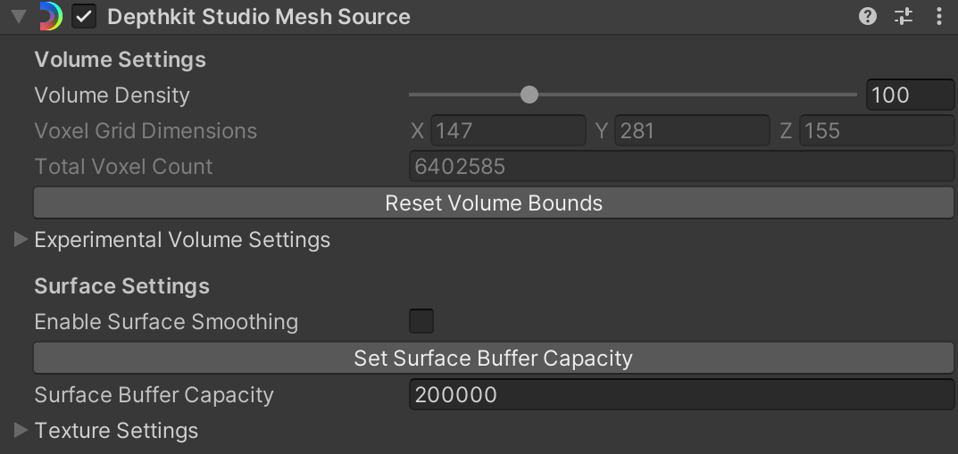
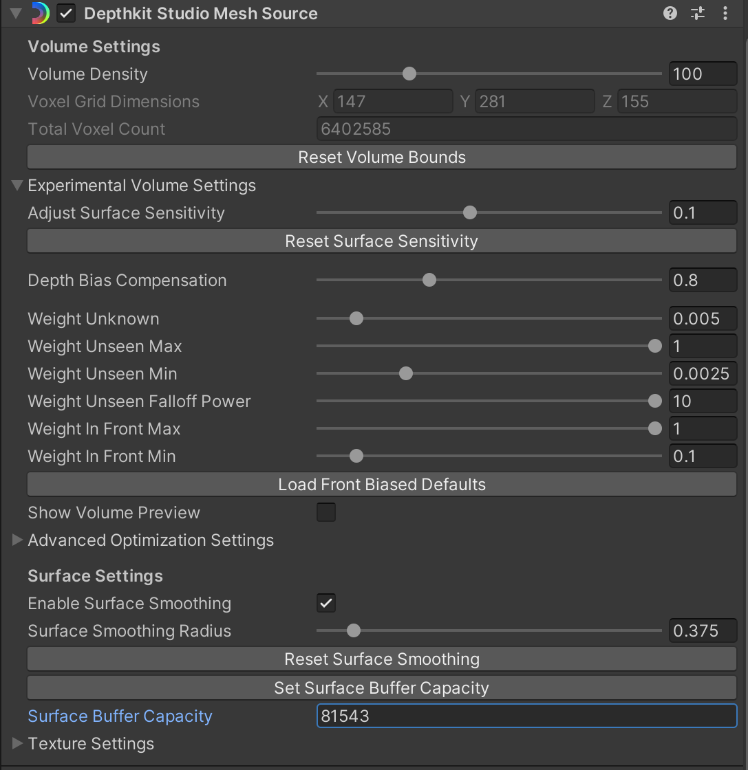
Once your Depthkit clip is positioned in your scene, there are a several handy settings that will significantly improve the quality and performance of your clip. These settings are located in the Depthkit Studio Mesh Source component.
Setting the volume bounds
📘 Bounding Box carried over from Depthkit app
As of Depthkit version 0.7.0, the bounding box set during Processing Studio captures is carried through to Unity. This means that once the bounding box is set in Depthkit, it doesn't need to be adjusted once in Unity.
Any assets which were exported in previous versions of Depthkit will still require adjustments to the bounding box in Unity.
The volume bounds scene view gizmo allows you to adjust the bounding box of your volume in order to control the volume density of your asset. This value acts as a key performance optimization. For best results, pull the bounds close to your subject without cropping the clip itself. Changing the volume bounds will adjust your Voxel Grid Dimensions as well as the Total Voxel Grid count, seen in the Depthkit Studio Mesh Source component under Volume Settings. It will not affect the size of each voxel just how many voxels are used to reconstruct your clip.
Use this gizmo in tandem with Volume Density to maximize performance and quality.
If at any point you need to reset these bounds, click the Reset Volume Bounds button.

📘 When adjusting the volume bounds, you may notice that your asset appears to clip.
Don't worry! Simply click Set Surface Buffer Capacity to reset the number of triangles generated for the clip.

Volume density
Adjust the volume density slider to optimize your mesh to suit your scene and intended publishing platform. This setting controls the resolution of the reconstruction volume and the number of voxels per meter. High mesh density maximizes the quality that your clip has to offer, especially when it comes to depth detail and edge quality. However, you may be building to a mobile device, in which case performance is key. In this scenario, you may rely on low mesh density.
Volume density units are represented as voxels per meter.
For best results, use Volume Density in tandem with the volume bounds to maximize performance and quality.
📘 When adjusting the volume density, you may notice that your asset appears to clip.
Don't worry! Simply click Set Surface Buffer Capacity to reset the number of triangles generated for the clip.
Experimental volume settings
These are experimental settings that control the mesh quality of your 3D asset. Volume settings will be unique to each clip.
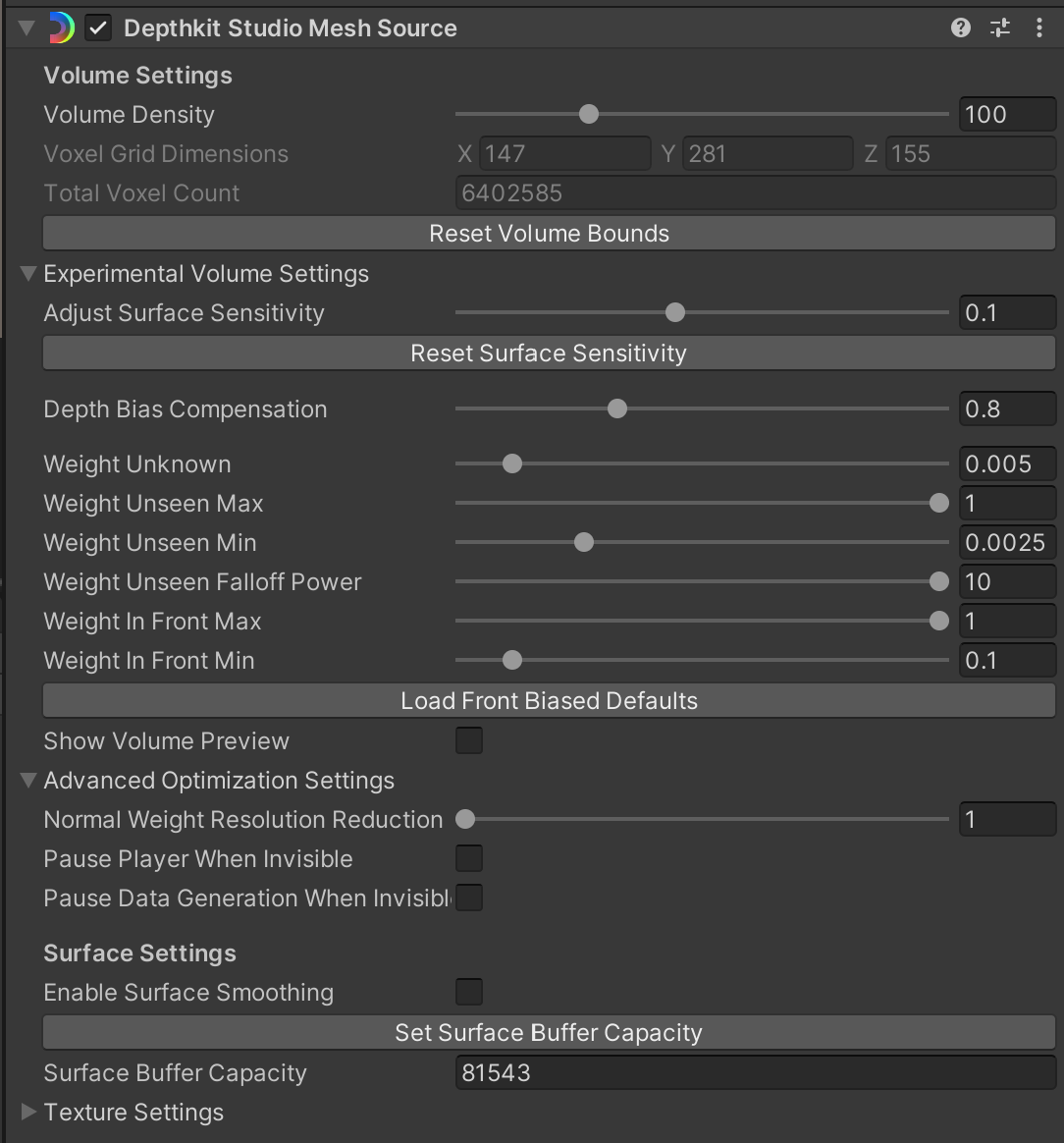
Adjust Surface Sensitivity takes into account your multiple depth perspectives and controls how to determine a given point in the depth data. A higher value is likely to bring out more depth and surface detail. For best results, increase this value as high as you can without introducing large artifacts.
📘 Volume settings will be unique to each clip.
The best overall strategy in refining any asset is to start with Adjust Surface Sensitivity. Find the value that represents the most detail and has minimal large artifacts. Small artifacts are acceptable at this stage and can be removed with volume settings below. Think of this as a starting point to set you up with the most data before moving ahead to the other settings.
Reset Surface Sensitivity will reset all experimental volume settings to the default values.
Depth Bias Compensation increases the accuracy and quality of your capture by correcting the material based bias found in many time of flight cameras. As of Depthkit version 0.7.0, the depth bias is applied to exported clips within the Depthkit app, and the resulting export factors this in. This means that any clips exported from this version or newer will need the Depth Bias Compensation to remain at 0. However, Depthkit Clips which were exported with a version of Depthkit prior to version 0.7.0 will likely need some amount (default: 0.8) of Depth Bias Compensation applied.
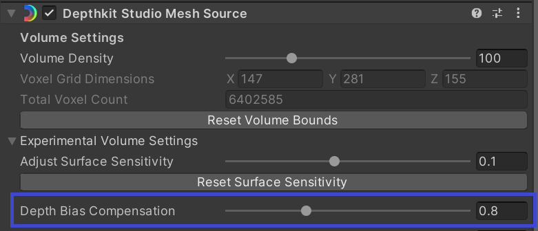
Time of flight devices measure some surfaces further away than they are in reality. The amount of bias depends greatly on the material of the surface being measured. Skin in particular has a large bias. The Depth Bias Compensation setting is a correction for this error by pulling the surface back towards their true depth. It is most useful for recovering high quality faces and hands. Accurate recovery requires a successful calibration.
The larger the value, the larger the compensation. 0 means no depth compensation bias applied. The default value is 0.8.
Weight Unknown is the starting value (weight) for a given voxel. Increasing this value expands the weight for areas inside the sensor frustum.
- When you have exported in Depthkit version 0.7.0 or newer, or have applied Refinement masks to your clip in an earlier version, you will get best results by increasing this value until you see artifacts.
- In contrast, if you have processed your clip in Depthkit version 0.6.2 or older without applying a mask, keep this setting at a low value. If the value is too high, you may notice depth holes being introduced.
Weight Unseen Max is the weight applied to voxels behind a surface. Max represents the value closest to the back of the surface, interpolated from Max to Min in Meters.
Weight Unseen Min represents the value at the distance contributed to the voxel behind a surface. This value becomes a 'floor' for all voxels behind the surface of a given perspective.
Weight Unseen Falloff Power maps between linear and quadratic curve from 1-10 (Linear-quadric) where 10 is the exponent. Increasing this values increases rate of falloff.
Weight in Front Max represents the ****ceiling of the weight for any voxel seen in front of a given surface. The way that it interpolates between min and max is based on the 3D distance to the camera as a multiplier. For best results, try setting this to a value of 1.
Weight in Front Min represents the floor of the weight for any voxel seen in front of a given surface. ****This value is multiplied by the distance to the camera.
Load Front Biased Defaults can provide a quick default configuration to get started with your volume settings.

Show Volume Preview allows you to preview the volume of your clip. The volume values are mapped to the HSV color range. This is useful for debugging what is happening with your look, if you see the correct data here, then its likely your problem is further down stream.
Enable this checkbox to reveal additional preview sliders.
- Volume Preview Alpha is the alpha of the preview points
- Volume Preview Point Size is the size of the preview points

Surface Settings
Enable Surface Smoothing reduces visual artifacts by applying a general smoothing to your clip. For best results, enable this setting after adjusting your volume settings for a final level of refinement. Avoid increasing the value too much to the point of over smoothing and eroding depth detail.

Set Surface Buffer Capacity allows you to define the maximum number of triangles that can be displayed for each frame of your clip. In other words, this sets the mesh size. Click the Set Surface Buffer Capacity button to sample the current frame to automatically determine a recommended value for your clip. This is helpful to reduce your memory footprint if you are using more triangle than needed.
You can manually edit this value as well. This can be valuable if your subject appears to be clipped. In this case, it may not have enough triangles. Increase this value to recover the missing mesh surface.
📘 Set your Surface Buffer Capacity after you make any changes to your volume settings, especially the volume density or volume bounds.
This will ensure the clip is running at maximum performance.
Texture Settings
These controls are related to how the current viewpoint is influencing the way in which the surface is reconstructed and drawn.
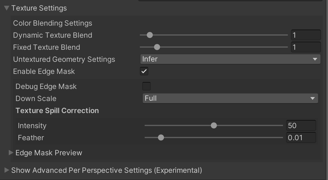
Color Blending Settings are applied at fragment shading time and will be shared out to all looks that are drawing this clip.
Dynamic Texture Blend This view-dependent weight is determined by taking a dot product of the view direction and the direction of each depth camera in the clip. This means that the weights will be higher for perspectives that the view point is more aligned with. The view weight is raised to this power for every view. The affect of raising this value means that the crossover time between per-view alignments is reduced, making for a snappier switch from one camera's color contribution to the next. A higher value results in less blending and a lower value will be more blended. The default value is 1.
Fixed Texture Blend. The view weight is mixed with the dot product of the surface normal and the perspective's camera direction. This product is raised to the power provided by this slider. The effect of raising this value is that the sensor perspective's contributions to the color can be dramatically influenced by which way the surface is pointed, causing sharp transitions from one perspective to another, based on surface normals.
- Values between 0 and 1 will emphasize overlap
- Values between 1 - 8 will deemphasize overlap
- Setting this to 0 effectively turn this contribution off completely.
- The Fixed Texture Blend can make blurry blends look sharper. However, it is heavily affected by the View Dependent Color Blending Weight, so it may be beneficial to balance these values.
Enable Edge Mask - Enable the edge mask feature to assist in blending harsh edges across perspectives. Enabling this setting will reveal a set of Edge Mask settings.
- Debug Edge Mask - Textures the mesh with a color-coded visualization of the mask generated per perspective for precise edge masking adjustments.
- Down Scale - Adjust the scale of the mask texture. Higher values capture more detail and have cleaner edges at the cost of performance.
- Texture Spill Correction - These values are loaded from the metadata for exports produced in Depthkit 0.7.0 and later
- Intensity - Corrects texture spill between surfaces, such as fragments of hands appearing on clothing.
- Feather - Softens texture spill correction. Needs to be adjusted visually and varies based on the Texture Spill Correction Intensity applied above.
Advanced per-perspective settings (experimental)
This is an advanced collection of settings that allow customization for each sensor perspective.
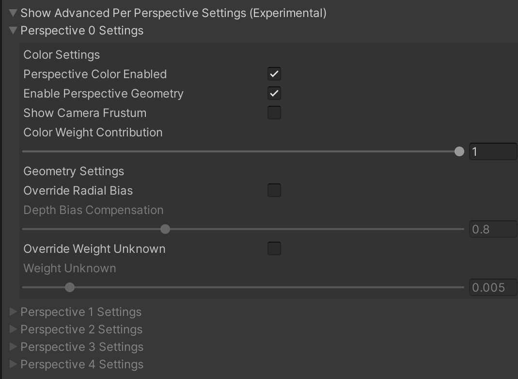
Color Settings → Perspective Color Enabled. Unchecking this option will turn off this perspective's color contribution to blending.
Show Camera Frustum. Will enable a frustum gizmo for this perspective only. This can be helpful for debugging view dependent issues.

Color Weight Contribution. The percentage that the global view dependent color weight affects this single sensor perspective. Setting this value to 0 will effectively turn off the view dependent contribution for this perspective.
Override Radial Bias Override the global value for Depth Bias Compensation per sensor.
Override Weight Unknown Override the global value for Weight Unknown per sensor.